· embedded · can-bus · reverse-engineering
Reverse-engineering a US$25,000 motor driver's CAN protocol with two Arduinos
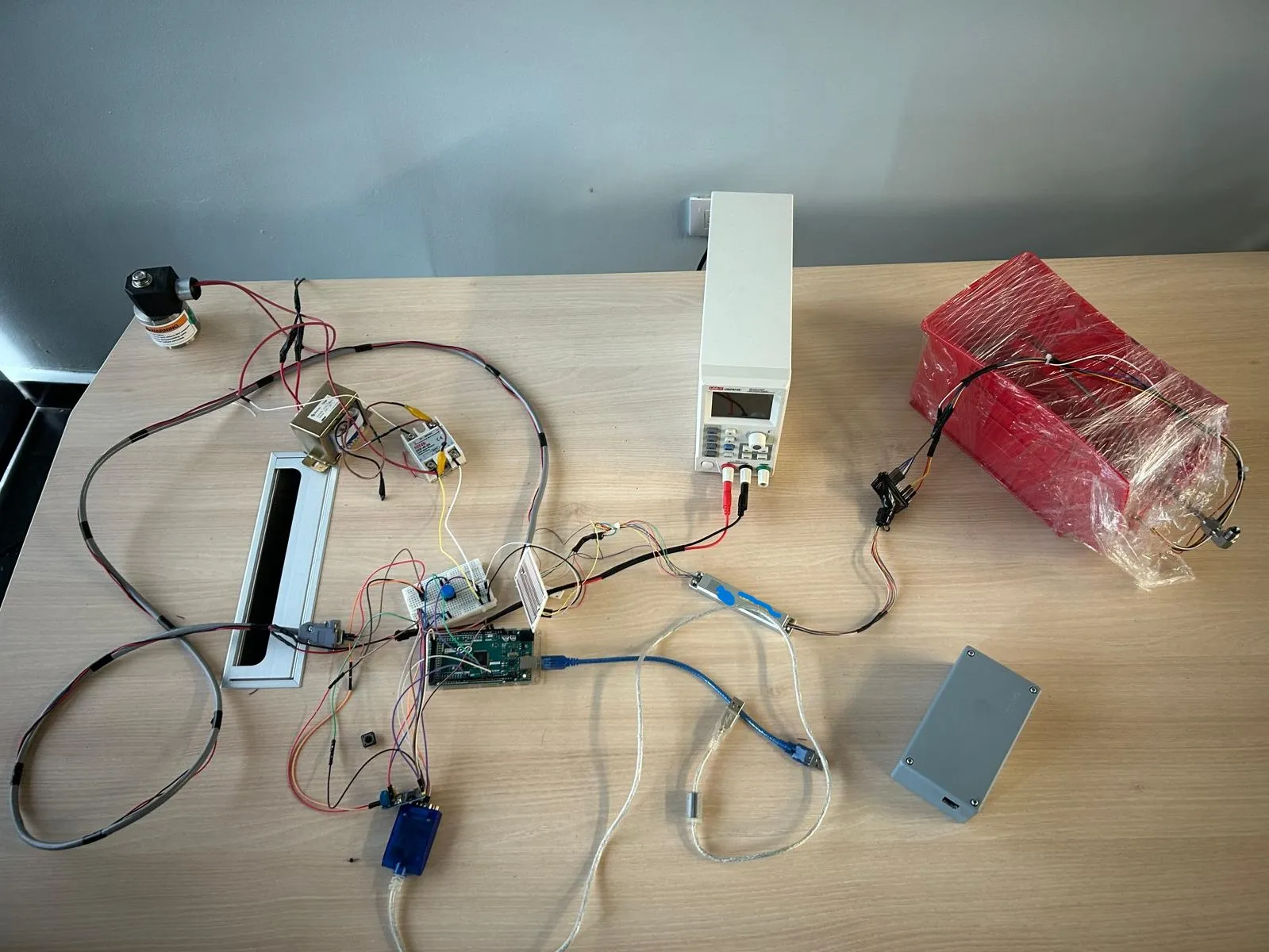
During my time as an Automation Engineer at Argos, an oil and gas automation company in Mexico, I ran into a wall: a motor driver that would only talk to its vendor’s software. The way through it was the approach that ended up defining that job for me: find the seam, script it.
The US$25,000 driver nobody could talk to
The team was working to bring microcontroller-based control into high-temperature, high-pressure downhole environments. For that purpose the company had purchased a motor driver rated for those conditions, valued at US$25,000. The problem was that driving it required either an even more expensive dedicated microcontroller, or a PC running the vendor’s proprietary software with an Arduino acting purely as a bridge to reach the driver.
In theory a third-party microcontroller could control the driver. In practice, the vendor’s support ended at sharing the meaning of each hexadecimal byte transmitted over the CAN bus. They never disclosed the actual communication protocol or the real control sequence the driver expected.
A man-in-the-middle made of Arduino
I was assigned the task of finding a way to control that motor driver directly from an Arduino over CAN bus. My approach was hands on: I set up a second Arduino as a man-in-the-middle between the PC and the driver, running a C script that intercepted the raw byte strings the proprietary software was sending and logged every frame to a text file.
With the captured traffic on one side and the vendor’s hexadecimal byte definitions on the other, I reverse-engineered the driver’s communication and control sequences and reproduced them in my own code. The result: a US$25,000 motor driver controlled from a standard Arduino over CAN bus, no proprietary software and no dedicated controller required.
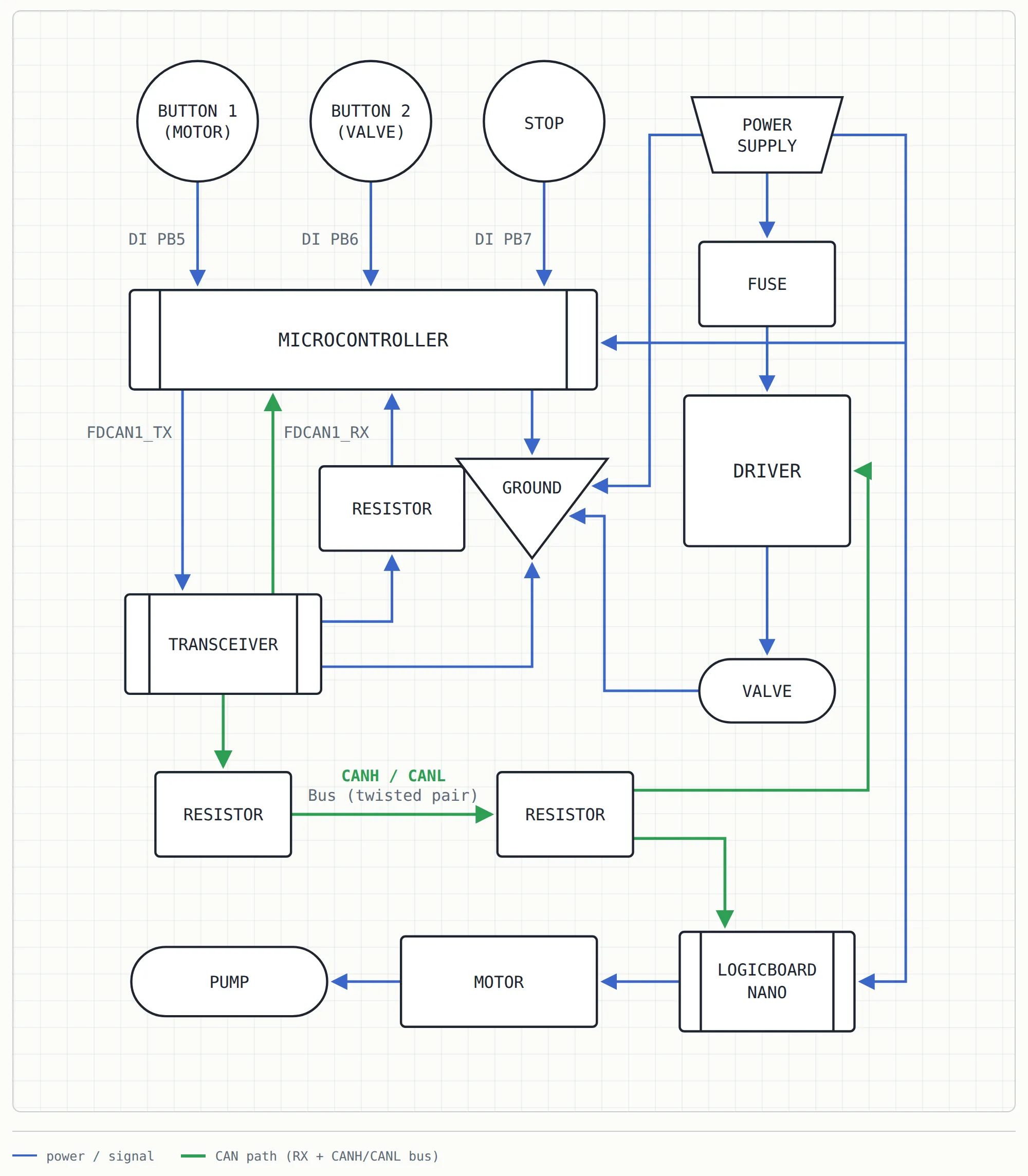
What I like most about this one is that it needed no exotic tooling. A spare Arduino, a C script, a log file and patience were enough to open up hardware that was effectively locked to one vendor’s stack.
Takeaway
A locked-down driver looks like a dead end, but somewhere underneath there is always a bus you can sniff. The devil is in the details, and the details are usually documented, one hexadecimal byte at a time.
Same job threw a very different bottleneck at me too — a SolidWorks drawing workflow that ate entire afternoons. That one got its own post: Automating SolidWorks drawing packages with VBA and Python over COM.