· mechatronics · manufacturing · digital-twin
Gripper, fixtures and a digital twin: designing a fixture-driven assembly cell
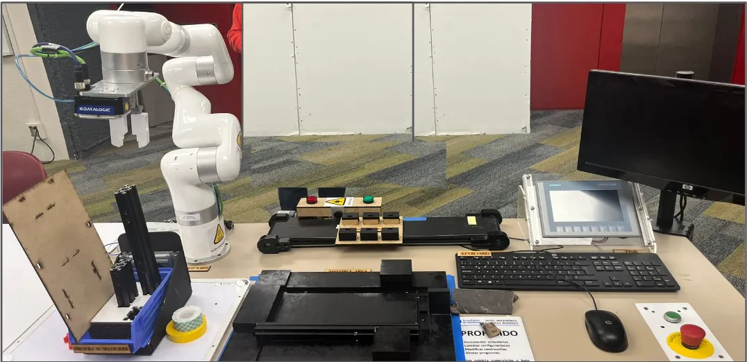
For our Manufacturing Automation module at Tecnológico de Monterrey, in partnership with MIT, a team of four of us built Station 1 of the FrED Factory: a semi-autonomous cell that assembles the structural base of MIT’s FrED (Fiber Extrusion Device) — three aluminium profiles, an MDF base plate and six PLA holders with TPU swivel locks — using a UFACTORY xArm 6, a Datalogic vision system and a Siemens PLC/HMI. The brief was to beat a manual-assembly baseline on cost and cycle time. My focus here is the mechanical side: the custom gripper, the fixtures that make robot teach-points repeatable, and the digital twin we used to validate the design.
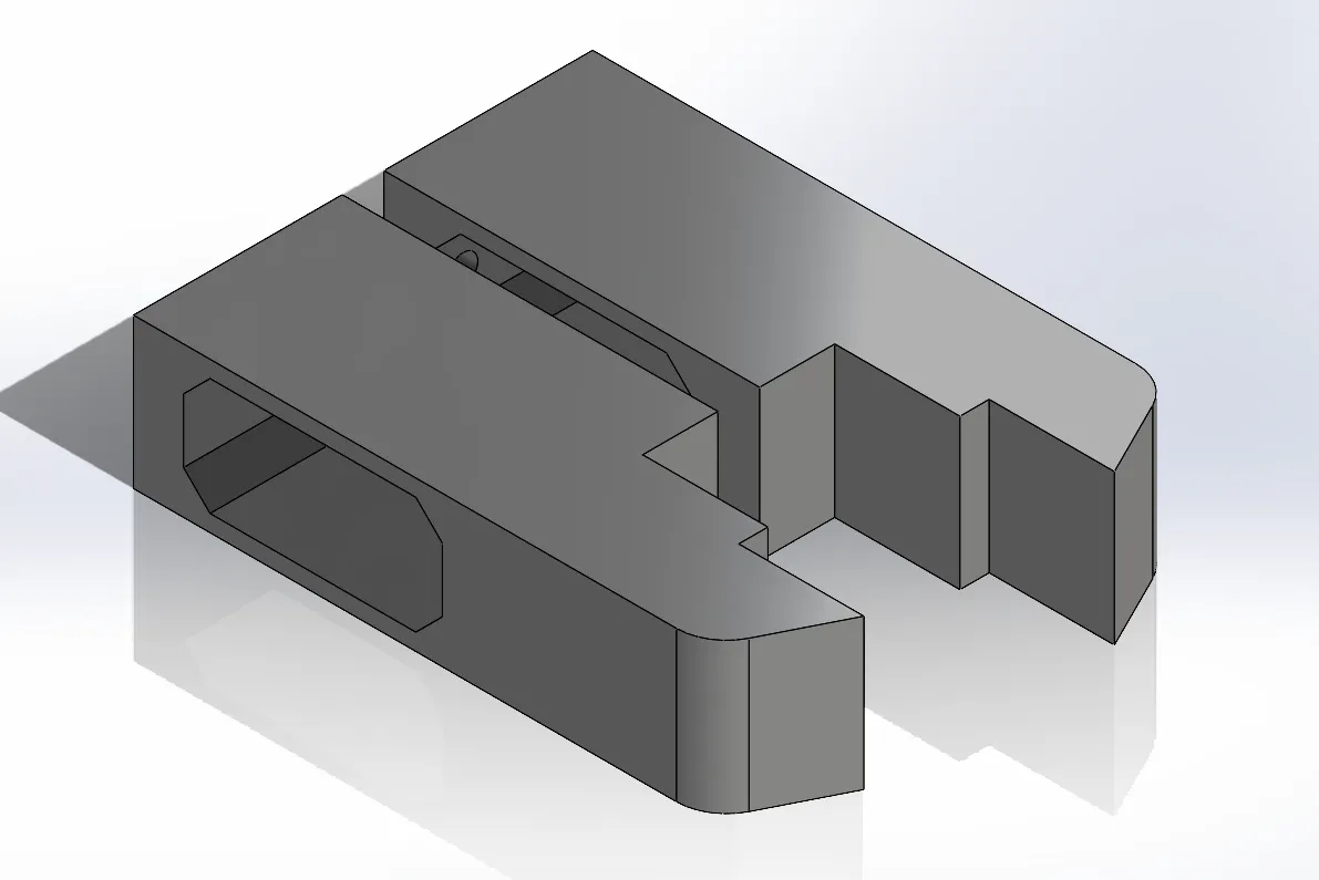
A gripper that took several iterations to get right
The xArm doesn’t ship with an end-effector for this job, so we designed one from scratch: a pneumatic jaw with three grip levels — a wider upper section for the MDF plate, a lower section for the PLA holders and swivels, and a third level so the same jaw handles both without re-tooling. It sounds simple on paper; getting there wasn’t. Air leaks, sealing problems and insufficient grip force forced several redesigns before it held parts reliably through a full cycle.
Fixtures: the unglamorous part that makes teach-points work
A taught robot only repeats what it was taught — if a part isn’t in exactly the same pose every time, the joint positions drift out of tolerance. We built four purpose-built fixtures: a holder fixture that presents the six PLA grip pieces to the robot on the conveyor, a 3D-printed T-lock system joining holders to profiles, a base fixture that locates the profile skeleton during assembly, and a profile storage unit sized and placed to minimize robot travel.
Measured cycle times
We instrumented every phase. Skeleton assembly (three profiles + MDF plate) ran 125.9 s; placing and locking the six holders ran 118.7 s; the full cycle including operator wait states came to 503.3 s — inside the 2-minute-per-station target the line set for each of its stations. Final inspection is vision-driven: on the HMI’s Inspection button, the robot sweeps all six holder positions and hand-shakes with a Datalogic camera at each one, which reports pass/fail back to the PLC.
Validating the design with a digital twin
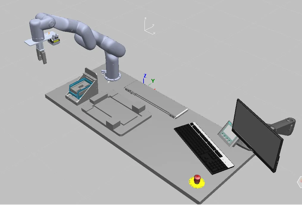
Alongside the physical build, we modeled the station in Siemens Plant Simulation to check throughput and material flow before committing to the physical layout. The simulation processed 245 finished units in the analyzed window at 41 units/hour, with 81.45% of a part’s time in the system spent adding value rather than waiting — evidence the layout and fixture sequencing weren’t leaving throughput on the table.
Code and full documentation (PLC ladder logic, vision system, Python control layer): github.com/PieroJF/Fred-Factory-xArm-robot-assembly-line.