· robotics · motion-planning · ros2
A* vs RRT vs PRM on one map — and the two bugs I found writing the README
For a motion planning and control (RMPC) coursework assignment, I solved the same navigation problem three times over: A* search on a kinematically constrained state lattice, RRT, and PRM — all against the same obstacle map — with the winning path handed to a time-optimal trajectory generator for a TurtleBot3-class differential-drive robot, targeting the ROS 2 / Nav2 stack. After the course I cleaned it up and published it as a standalone reference implementation. The most valuable part of that step was not the polish. It was rereading my own code to write the README — and finding two real bugs, which I documented publicly instead of quietly patching over.
Three planners, one map
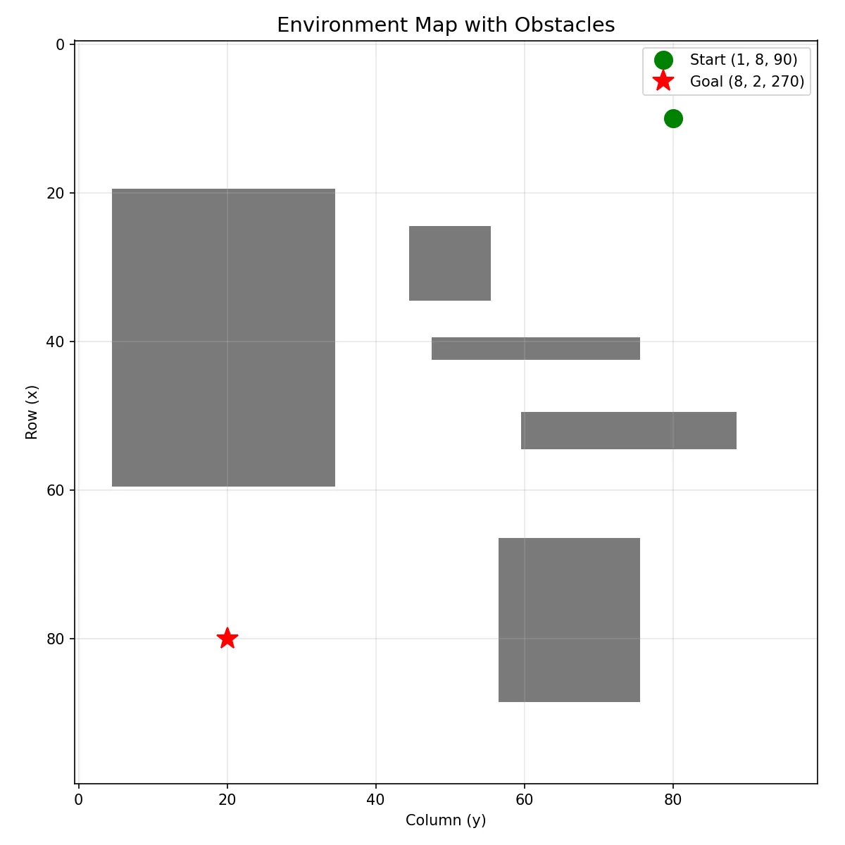
The lattice planner discretizes the robot’s state space into a 10×10 cell grid times 4 headings — 400 vertices — connected by motion primitives a diff-drive robot can actually execute. A* with an admissible heuristic finds the optimal route: a 9-vertex path threading between the five obstacles.
The sampling-based planners attack the same problem from the continuous side. RRT grows a 331-node tree from start toward goal; PRM builds a reusable roadmap of 202 nodes and 1,114 edges, with a KDTree answering nearest-neighbor queries. The stack underneath is deliberately minimal — NumPy, SciPy, Matplotlib, PyYAML — so every step is easy to audit and reproduce.
From a path to a trajectory
A list of waypoints is not something a robot can execute. The trajectory generator resamples the winning path and lays a trapezoidal velocity profile over it, producing a full (x, y, θ, v, a, ω) trajectory with optional YAML export for a Nav2 launch file. One honesty note, also stated in the README: the rclpy and geometry_msgs imports are scaffolding for a future live node — nothing spins up a ROS 2 node yet.
Bug #1: two planners quietly solving an easier problem
Writing the architecture section of the README meant re-tracing how the start and goal
flow through main.py. That is where it stopped adding up. The same tuples — (1, 8, 90)
and (8, 2, 270) — are cell indices for the lattice planner, scaled by a cell size of 10
onto the 100×100 map. But they are also passed, unscaled, straight into the RRT and
PRM constructors, where they are read as continuous (x, y) coordinates on that same
100×100 map.
So A* was solving the real problem — the long diagonal crossing past all five obstacles — while RRT and PRM were solving a trivial ~10-unit hop near the top-left corner. It explains something I had looked at many times without seeing: the comparison figure shows a big exploration tree and a dense roadmap, but paths that are almost invisible. The benchmark I thought I had built was silently apples-to-oranges.
Bug #2: a velocity limit that never limits anything
The second one is subtler. The trajectory generator declares omega_max = 2.8 rad/s in
its constructor — and then never uses it. The angular velocity that comes out of
resampling is purely the finite difference of the interpolated heading; nothing clamps it
against the declared limit. The velocity profile figure makes the consequence visible:
spikes above 6 rad/s — more than double the stated limit — at the arc-transition
instants around t ≈ 5 s, 17 s, and 39 s. On a real robot those commands would saturate,
and the executed path would drift away from the planned one exactly where the geometry is
hardest.
Neither bug ever threw an exception. Both produced plausible-looking figures. Both only surfaced because writing documentation forced me to read the code as an outsider.
Why I published the bugs instead of fixing them silently
The tempting move when polishing a portfolio repo is to scrub the flaws and present a seamless artifact. I did the opposite: the README has a “Design Notes & Known Limitations” section that walks through both bugs — plus an O(V) neighbor-expansion inefficiency in the A* solver that is fine at 400 vertices but would need an adjacency list to scale.
I think that is the stronger portfolio signal. Anyone can make a demo look like it works; the plots here genuinely look fine. What is harder to fake is the ability to re-read your own code critically, catch what the pretty figures hide, and explain precisely why it is wrong and what the fix would be. A repo with documented flaws tells a reviewer how I think. A repo with hidden ones just tells them I can generate figures.
The code, the figures, the planner comparison table, and both bug write-ups are all here: github.com/PieroJF/lattice-motion-planning-ros2.